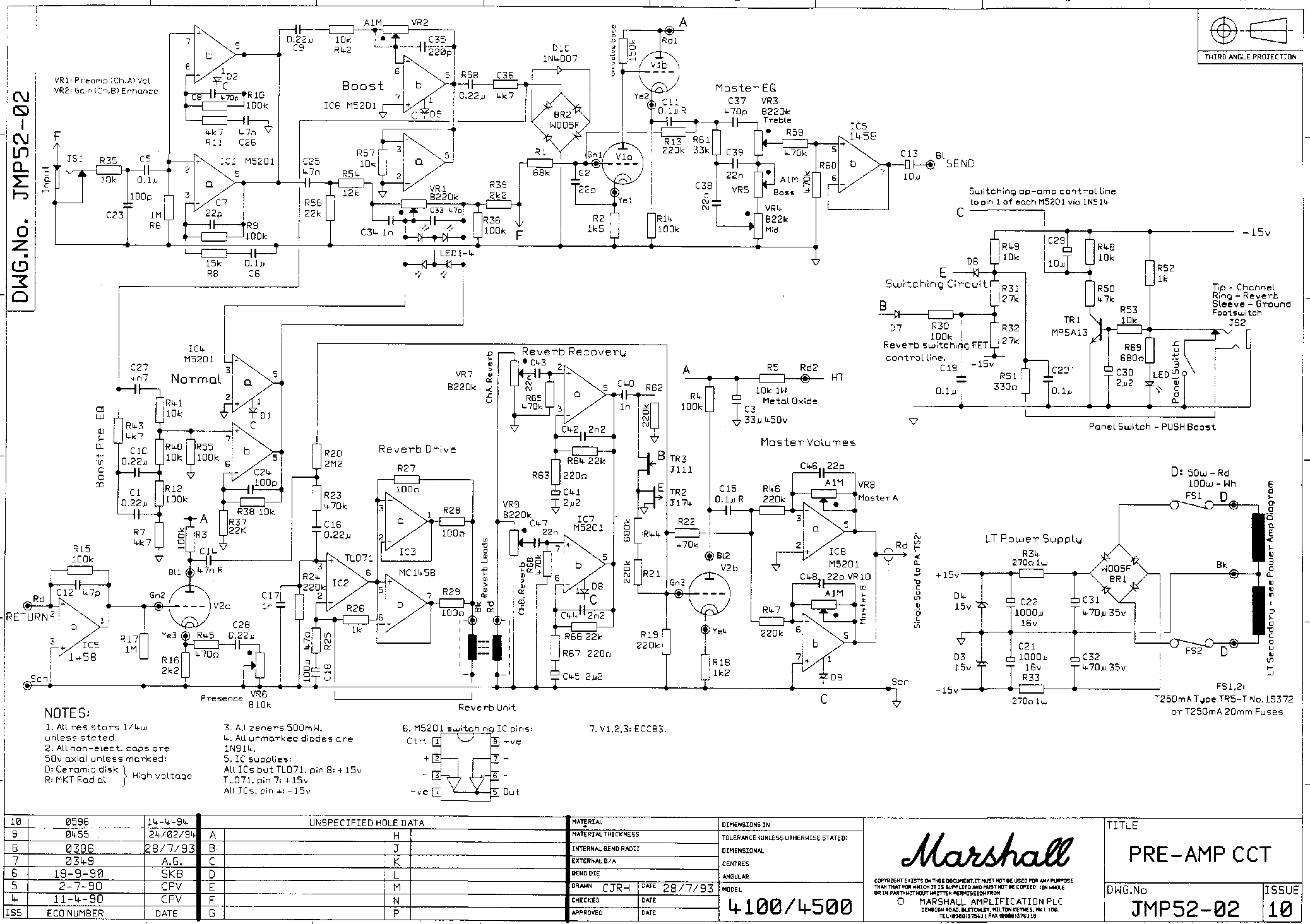
I found this article and I thought some good stuff might come of it. In the thread they are talking about how Marshall JCM 900's used "Bridge Rectifiers" for clipping instead of the regular LED's used in the 800's
The 900's are kind of fuzzy and I thought we might be able to capitalize in the bridge rectifiers for some home brewed fuzz pedals.
I can't find many good schematics of how to wire one up
has anyone had any experience with using a bridge rectifier in place of regular clipping diodes?
Thanks
here is the thread that talks about it.
http://music-electronics-forum.com/t5984/
JCM 900 Distortion in a pedal?
Moderator: The Captain
- HydrozeenElectronics
- Posts: 242
- Joined: Thu Nov 27, 2008 3:27 am
- Location: Astoria Oregon
- SonicVI
- Posts: 2611
- Joined: Fri Jan 09, 2009 8:13 pm
- Location: Houston, TX
Re: JCM 900 Distortion in a pedal?
HEre's the schematic of one of the JCM900's. The bridge rectifier is the ring of diodes between the first two preamp tubes. You'll also see a rectifier in the power section on the bottom right. This is where you usually find them.


"If you want to write rock lyrics you must learn about where the Hobbits dwell."
- HydrozeenElectronics
- Posts: 242
- Joined: Thu Nov 27, 2008 3:27 am
- Location: Astoria Oregon
Re: JCM 900 Distortion in a pedal?
SonicVI wrote:HEre's the schematic of one of the JCM900's. The bridge rectifier is the ring of diodes between the first two preamp tubes. You'll also see a rectifier in the power section on the bottom right. This is where you usually find them.
thanks, that's a great schematic that will really help me out.
Who is online
Users browsing this forum: No registered users and 1 guest
