I'm attempting to trace the Top Gear - Fuzz Sustain pedal. Below are the pictures I've used (all found on the internet) and the schematic I came up with.
Is there anyone willing to check to see if my schematic is correct or give me hints to what might be incorrect?
Also, perhaps someone can confirm the component values and fill me on the missing values?
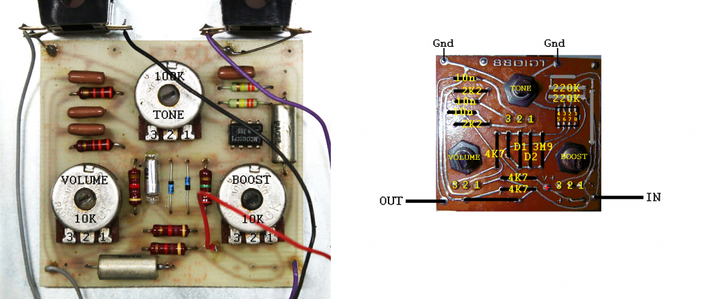
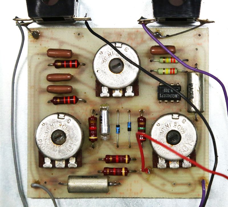
- IC is stamped MCI741ISCP. Other units use UA741TC.
- Resistors SHOULD all be correct. Boost and Volume are 10K, but the Tone pot is hard to read and looks like 100K.
- The polystyrene cap value can't be seen, but my guess is in the pF range.
- In pics of another unit, the tropical fish caps look like 10nF, but I am not 100% positive.
***Schematics are on page 3, including one from Leon!***