Page 1 of 6
Help Tracing a Top Gear - Fuzz Sustain
Posted: Wed Sep 26, 2012 5:31 pm
by FUZZTX
Hey guys!
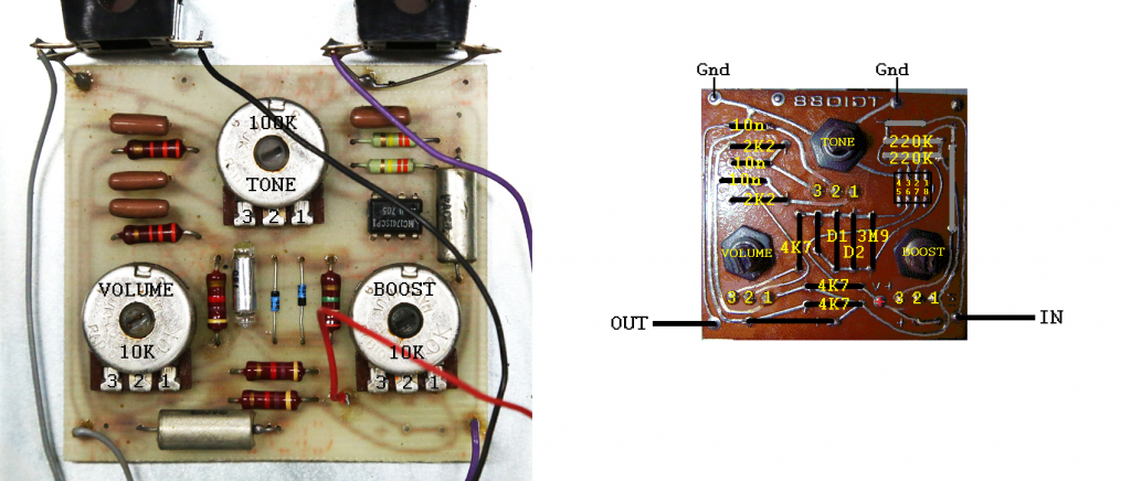
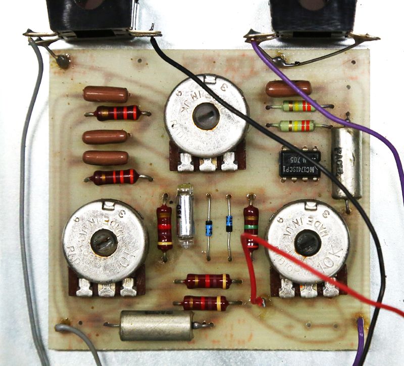
I'm attempting to trace the Top Gear - Fuzz Sustain pedal. Below are the pictures I've used (all found on the internet) and the schematic I came up with.
Is there anyone willing to check to see if my schematic is correct or give me hints to what might be incorrect?
Also, perhaps someone can confirm the component values and fill me on the missing values?
- IC is stamped MCI741ISCP. Other units use UA741TC.
- Resistors SHOULD all be correct. Boost and Volume are 10K, but the Tone pot is hard to read and looks like 100K.
- The polystyrene cap value can't be seen, but my guess is in the pF range.
- In pics of another unit, the tropical fish caps look like 10nF, but I am not 100% positive.
***Schematics are on page 3, including one from Leon!***
Re: Help Tracing a Top Gear - Fuzz Sustain
Posted: Wed Sep 26, 2012 7:24 pm
by LucifersTrip
somebody released a clone called Paisley Fuzz Sustain...and they noted it was very similar to a DOD250

Posted: Wed Sep 26, 2012 7:42 pm
by FUZZTX
Thanks, LucifersTrip! I do see the similarities.
I do now see one possible mistake in my schematic. It looks like lug 1 of the Volume should go to ground, as well as the 4K7 that I have connected to it to +9V. Looks like that 4K7 should be between ground and +9V, possibly part a bias network or whatever like in the DOD 250.
Posted: Wed Sep 26, 2012 7:58 pm
by FUZZTX
* Removed old schematic.
Re: Help Tracing a Top Gear - Fuzz Sustain
Posted: Wed Sep 26, 2012 8:02 pm
by Dr Tony Balls
Thats more similar to a Tube Screamer than it is a DOD 250 with the diodes in the feedback loop like that,
Re: Help Tracing a Top Gear - Fuzz Sustain
Posted: Wed Sep 26, 2012 8:27 pm
by John Lyons
I didn't trace it but pin two needs a ground reference for the IC to operate with gain.
See how the 250 schematic goes pin 2 > .047 > 47k > variable 500k to ground.
You will need something like that.
Are you sure pin 2 and 3 are connected (indirectly)?
Re: Help Tracing a Top Gear - Fuzz Sustain
Posted: Wed Sep 26, 2012 8:54 pm
by FUZZTX
John Lyons wrote:I didn't trace it but pin two needs a ground reference for the IC to operate with gain.
See how the 250 schematic goes pin 2 > .047 > 47k > variable 500k to ground.
You will need something like that.
Are you sure pin 2 and 3 are connected (indirectly)?
Thanks, John! I am going to retrace those sections, but I did think 2&3 were connected, which is weird. Now that I think about it, it doesn't make sense.
Re: Help Tracing a Top Gear - Fuzz Sustain
Posted: Thu Sep 27, 2012 2:41 am
by FUZZTX
Ok, I retraced the front section and now this is what I am seeing. Not sure about the 220K to ground on the input though.
*Updated schem in first post.
Re: Help Tracing a Top Gear - Fuzz Sustain
Posted: Thu Sep 27, 2012 4:39 am
by John Lyons
That looks better. But, the IC needs to be biased somehow.
Generally you have a voltage reverence divider like the 250s 20k/20k/470k at the input pin 3.
Or you could use a divider like 100k/100k one to ground and one to +9v at the input.
By chance is there another 220K to +9v at the input?
The boost section looks odd with that 220k at least.
I just don't have time to trace it at the moment.
Posted: Thu Sep 27, 2012 6:57 pm
by FUZZTX
John, I appreciate your tips!
The biasing is one thing that confuses me. I see how one 220K resistor could go to ground through lug 1 of the boost pot, but the only resistor I see connecting to +9V is the 4K7 coming off lug 1 of the volume pot. The other 220K resistor looks like it connects to pin 3 of the op amp then possibly to ground through lug 1 of the boost pot.
Grrrr! It shouldn't be this hard, but I don't know op amp circuits very well.
Sorry, guys! I was hoping to have a schematic for the forum, but this is going to be slowing going for me! I don't think I have the tone circuit correct either!