Page 1 of 6
SupaFuzz MK1 schematic and layout
Posted: Fri Jul 31, 2009 1:16 am
by SonicVI
For those of you who didn't see this in the Sound and Vision forum.
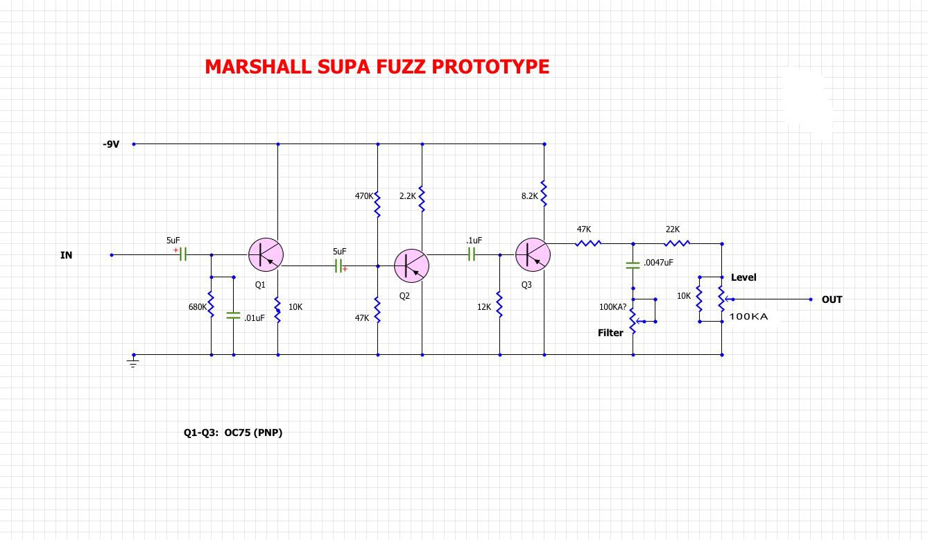
This is the schematic (unverified) of the earliest Marshall SupaFuzz. It's basically a MK1 with a high-pass filter on the end.
There's info about it in Graham's SupaFuzz Data Dump thread here:
viewtopic.php?f=23&t=157
schematic:
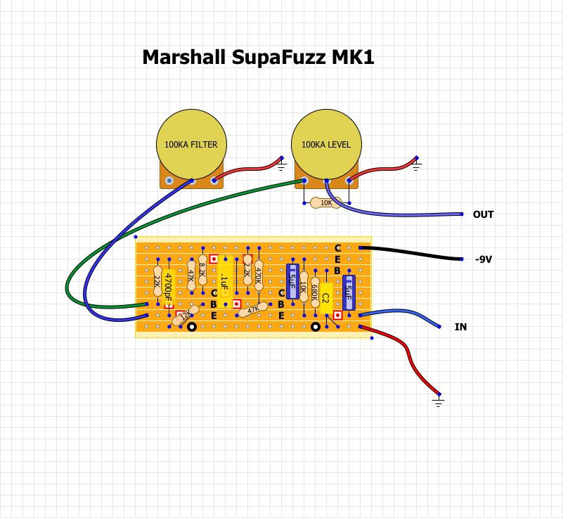
Layout:
Re: SupaFuzz MK1 schematic and layout
Posted: Fri Jul 31, 2009 7:57 am
by Electric Warrior
good one

Re: SupaFuzz MK1 schematic and layout
Posted: Fri Jul 31, 2009 9:17 am
by tatter
Excellent work! I've wanted to know about this pedal ever since i read the Tone Bender History page, thanks!
Re: SupaFuzz MK1 schematic and layout
Posted: Fri Jul 31, 2009 10:28 pm
by FOXFIRE
no output cap?
Re: SupaFuzz MK1 schematic and layout
Posted: Sat Aug 01, 2009 12:20 am
by Stu
FOXFIRE wrote:no output cap?

Re: SupaFuzz MK1 schematic and layout
Posted: Sat Aug 01, 2009 2:25 am
by analogguru
FOXFIRE wrote:no output cap?
schematic and layout are simply wrong..... the 4n7 is not a filter cap instead it is the output cap.
the filter potentiometer acts as a voltage divider in conjunktion with the 47k and 22k resistor.
Have a look at the guts again.
BTW, OC75 are pnp transistors and NOT npn as shown. The second 5µF electrolytic is drawn in the wrong direction.
analogguru
Re: SupaFuzz MK1 schematic and layout
Posted: Sat Aug 01, 2009 2:37 am
by SonicVI
analogguru wrote:FOXFIRE wrote:no output cap?
schematic and layout are simply wrong..... the 4n7 is not a filter cap instead it is the output cap.
the filter potentiometer acts as a voltage divider in conjunktion with the 47k and 22k resistor.
Have a look at the guts again.
BTW, OC75 are pnp transistors and NOT npn as shown. The second 5µF electrolytic is drawn in the wrong direction.
analogguru
I noted in the other thread about the transistors. I couldn't make them PNP with the emitters pointing down in DIY Layout Creator so I just used the NPN symbols. We all know it uses OC75's and well all know they are PNP so I didn't really care.
Re: SupaFuzz MK1 schematic and layout
Posted: Sat Aug 01, 2009 3:02 am
by analogguru
SonicVI wrote:
I couldn't make them PNP with the emitters pointing down in DIY Layout Creator....
Really ? Did you search on your computer for a program called "paint" ?
Temporarely available for your files:

analogguru
Re: SupaFuzz MK1 schematic and layout
Posted: Sat Aug 01, 2009 3:05 am
by SonicVI
No, I don't have Paint.
Thanks for the corrections. I'll make the changes in my project. I'll flip the wires on the layout as well.
Re: SupaFuzz MK1 schematic and layout
Posted: Sat Aug 01, 2009 3:38 am
by analogguru
SonicVI wrote:
No, I don't have Paint.
If you have Windows98 or XP you will have it as a windows-tool - for free.
analogguru