Garrett Fuzz Unit
Moderator: The Captain
-
Jim Goad

- Posts: 3457
- Joined: Thu Aug 28, 2008 4:23 pm
- Location: Oxfordshire UK
Re: Garrett Fuzz Unit
Such a badass looking fuzz. Would love to hear it.
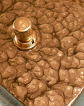
It's like an orange on a toothpick
-
Nick

- The Artist Formerly Known As nightraven
- Posts: 2237
- Joined: Tue Dec 01, 2009 7:25 pm
Re: Garrett Fuzz Unit
Amazing score! That thing looks super radical!!
I can't get enough of the seemingly endless supply of obscure 60s fuzzboxes that are still resurfacing
I can't get enough of the seemingly endless supply of obscure 60s fuzzboxes that are still resurfacing
-
jerms
- Posts: 5629
- Joined: Sun Mar 01, 2009 10:39 pm
- Location: back in the basement!!
Re: Garrett Fuzz Unit
thank god it didn't end up in the trash!!!
-
AmplifiedPartsTom
- Posts: 5
- Joined: Sun Oct 30, 2022 11:23 pm
Re: Garrett Fuzz Unit
Hi folks, I think I have the schematic for this one based on moose's (fantastic) pics. I've tried to decipher schematics from gut pics before and it's always tough to find great photos of rare stuff. Awesome to have such great pics of a fuzz I've never seen elsewhere, so thanks for that moose. That being said, I definitely can't guarantee I got this right, but I feel pretty good about it especially because the resulting schematic makes sense to me and there wasn't much guesswork.
Here's what I know I don't know:
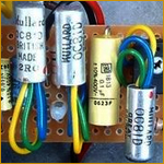
Regarding the diodes, the gold leads are kind of unusual so that might be a way to help narrow down results if anyone is interested in trying to figure out the exact type. I'm hoping someone recognizes the logo on them. Moose, if you have a multimeter and are willing to do so, the voltage drop of those diodes can be measured in-circuit with the effect engaged. I'd probably remove the battery, but you shouldn't have to. With the effect disengaged, both sides of the diodes are common so you won't get a reading.
I have not built this yet, but plan to soon. I'll report back. Also attaching a pic with some of moose's gut shots and my component reference values in the schematic.
Here's what I know I don't know:
- I don't know what the volume pot value is.
- Not sure what the diode type would be, and I don't recognize the logo on them. They look like diodes that would be marketed as rectifier diodes, and I'd lean silicon based on the look, but that's a pretty wild guess.
- I put 2N1307 in the schematic based on moose guessing 2N1306, but that's just an arbitrary choice. They do look exactly like 2N1307s I've seen, but also plenty of other TO-5 types. They are PNP transistors, tab marks emitter. Gold pin obviously, for whatever that's worth.
- I'm assuming 9V battery here, but it's not visible in the photos.
- R5 looked like a Red Brown Orange Gold resistor (21K) to me. I changed it to 27K because the values surrounding Q1, Q2 and Q3 are identical otherwise, and Q2 and Q3 both use 27K there. That's a more common value, and I could see the "brown" band actually being a faded violet band, which would make it 27K. I think that's more likely.
- I don't believe the value of caps C1, C5, or C9 is visible in any of the photos. I can kind of make out C5 and it looks like it's probably 50, but I'm not 100% sure. 50u seems likely for all 3, but confirmation would be awesome.
Regarding the diodes, the gold leads are kind of unusual so that might be a way to help narrow down results if anyone is interested in trying to figure out the exact type. I'm hoping someone recognizes the logo on them. Moose, if you have a multimeter and are willing to do so, the voltage drop of those diodes can be measured in-circuit with the effect engaged. I'd probably remove the battery, but you shouldn't have to. With the effect disengaged, both sides of the diodes are common so you won't get a reading.
I have not built this yet, but plan to soon. I'll report back. Also attaching a pic with some of moose's gut shots and my component reference values in the schematic.
- Attachments
-
- garrett_fuzz_unit_schematic.jpg (113.87 KiB) Viewed 768 times
-
- garrett_trace.jpg (307.91 KiB) Viewed 768 times
Last edited by AmplifiedPartsTom on Mon Oct 31, 2022 3:34 am, edited 1 time in total.
-
AmplifiedPartsTom
- Posts: 5
- Joined: Sun Oct 30, 2022 11:23 pm
Re: Garrett Fuzz Unit
Some general thoughts on the circuit:
The top portion is the fuzz section, the bottom portion is a clean boost. Normally with the effect engaged, the signal is running through both sections and being mixed at the output. Attack controls the level of the fuzz output, while Volume controls the level of input to the clean boost (effectively a volume control for only the boost section). So with volume turned all the way down, you will still get output (just the fuzz output) depending on the Attack level. Moose, can you tell me if that's how your unit works? That would help confirm I got all the footswitch connections correct, which is one of the areas I'm not 100% on.
If my drawing is correct, with the effect disengaged, the signal still goes to the fuzz input but the output of the fuzz section is grounded so no fuzz bleeds out. The signal is still going through the clean boost section, only now the Volume pot (which is an input attenuator for the clean boost section) is bypassed. Neither pot does anything when disengaged, which makes sense, but the way the Volume control is being bypassed makes it so that the clean boost section cannot be louder with the effect engaged than it is with the effect disengaged. The overall output level can be higher with the fuzz added though.
The fuzz section is kind of an interesting 2-transistor circuit. The biasing is more sophisticated than a Fuzz Face with Q1 and Q2 DC bias being isolated from each other by C4, and they use a voltage divider on each base which should be quite a bit more temperature stable. There's also no feedback from Q2E to Q1B, which is unlike the FF. Of course the clipping diodes are probably the most noticeable difference. I'd be curious to hear the circuit both with and without those, although it's probably going to be extremely loud without the diode voltage drop. The fuzz face attenuates the signal a ton with the voltage divider on Q2C, but that's not done here.
-
edkoppel
- Posts: 3303
- Joined: Fri Oct 16, 2009 10:32 pm
- Location: Nashville, TN
Re: Garrett Fuzz Unit
Whoa!
I want that!
I want that!

Oh, DB? That's just slang for Dandy Big muff collector.
-----------------------
Tone Machines, Vintage Effects Blog: www.tonemachinesblog.com
Instagram: https://instagram.com/ed_skymall
-----------------------
Tone Machines, Vintage Effects Blog: www.tonemachinesblog.com
Instagram: https://instagram.com/ed_skymall
-
HorseyBoy

- Posts: 4135
- Joined: Mon Oct 15, 2012 10:48 pm
- Location: Harlan County
-
Zuff-1A

- Posts: 1271
- Joined: Wed Oct 26, 2011 2:55 pm
- Location: Estonia, Tallinn
Re: Garrett Fuzz Unit
Cool project  good luck with that
-
moose

- Posts: 619
- Joined: Tue Jun 09, 2009 10:03 pm
- Location: Dublin
Re: Garrett Fuzz Unit
Hey I still have the unit and a partially drawn trace so will get back on later in the week with the missing info and more pics. From memory it looks right in that it's three identical circuits in series. Nice work.
-
AmplifiedPartsTom
- Posts: 5
- Joined: Sun Oct 30, 2022 11:23 pm
Re: Garrett Fuzz Unit
Thanks moose, that would be a big help. I think I'll have this wired up either tonight or tomorrow and can report back with my thoughts/findings.
Who is online
Users browsing this forum: Hoylehill, Semrush [Bot] and 9 guests