sounds plausible.
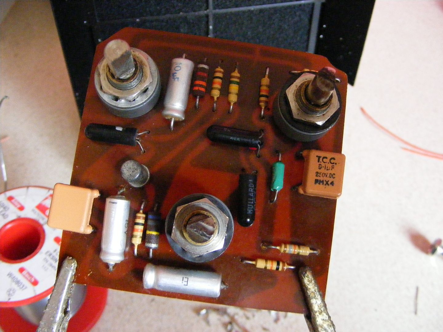
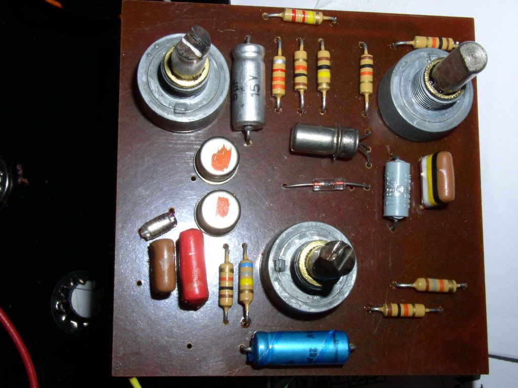
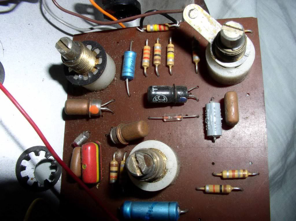
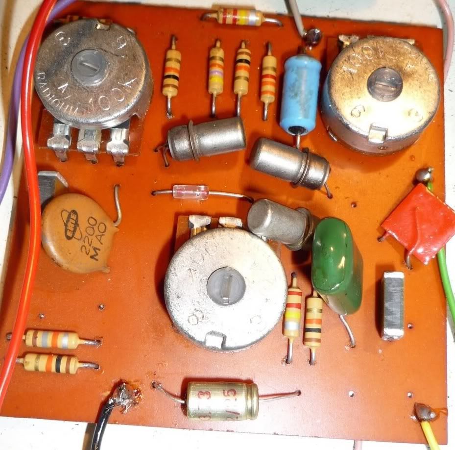
That 25µF electrolytic sure is unusual. What about that 1M resistor? That's not stock, is it?
Rotosound Mark III
Moderator: The Captain
-
Electric Warrior

- Posts: 3620
- Joined: Sun Nov 09, 2008 2:19 am
-
The Captain

- Posts: 7014
- Joined: Tue Aug 26, 2008 12:05 am
- Location: UK, Earth
Re: Rotosound Mark III
Yah, bare in mind the Dizzytone, or a least some of 'em, had the 25uf cap there too.
No, the 1M is a modern carbon comp. The original part there was a 1M carbon comp resistor though....it was a tad high on goof balls and reading around 3-4 Meg! ...so it had to go.
No, the 1M is a modern carbon comp. The original part there was a 1M carbon comp resistor though....it was a tad high on goof balls and reading around 3-4 Meg!
-
Electric Warrior
- Posts: 3620
- Joined: Sun Nov 09, 2008 2:19 am
Right, but it's still unusual in a Colorsound made MKIII/IV/V, isn't it? Maybe they were out of 5µF caps that day or Rotosound ordered slightly different specs. Who knows?
I haven't seen any other MKIII/IV/Vs with 25µF and 1M in these particular spots yet. have you?
are you sure the resistor was a carbon comp, btw? AG thinks these are carbon film: http://stompboxes.co.uk/forum/viewtopic ... &start=550
Guess they would be impossible to tell apart if there was a carbon film and a carbon comp variant.
Everything is transitional.
-
The Captain
- Posts: 7014
- Joined: Tue Aug 26, 2008 12:05 am
- Location: UK, Earth
Re:
1M for sure...25uf, I'll have to check my pics n such...Electric Warrior wrote:I haven't seen any other MKIII/IV/Vs with 25µF and 1M in these particular spots yet. have you?
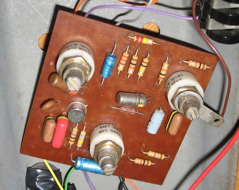
Think so. It was just like the 680k one on this board...Electric Warrior wrote:....are you sure the resistor was a carbon comp, btw?
-
Electric Warrior
- Posts: 3620
- Joined: Sun Nov 09, 2008 2:19 am
-
analogguru
- Posts: 527
- Joined: Sun Oct 26, 2008 12:54 pm
Re: Rotosound Mark III
The value of the bypass doesn´t have so much influence on the fuzz sound as the 220n coupling cap which is here a 10µF electrolytic or so.
BTW, a 1M resistor together with a 100k to ground as bias divider is a little bit strange. Normally there should be a 680k when a 100k to ground is used.
Let´s assume the circuit is normally biased at the collector of the second transistor to 6 - 7 V. Let´s take 7V, which leads to the result that at the emitter resistor will be lost ~ 700 mV, plus 200 mV BE loss at the second transistor, + 200mV BE loss at the first transistor = 1,1V - needed at the base of the first transistor to conduct. With a 1M resistor there would be only max. 0,9 V.....
Now lets calculate reverse:
400mV for the transistor junctions would lead to a remaining voltage of max. 500mV at the emitter resistor of Q2. Therefore the voltage drop at the collector resistor can only be max. 1,5 V leading to a collector voltage of 7,5 V at the best.
analogguru
-
theemadcap1
- Posts: 985
- Joined: Sat Sep 20, 2008 11:25 pm
Re: Rotosound Mark III
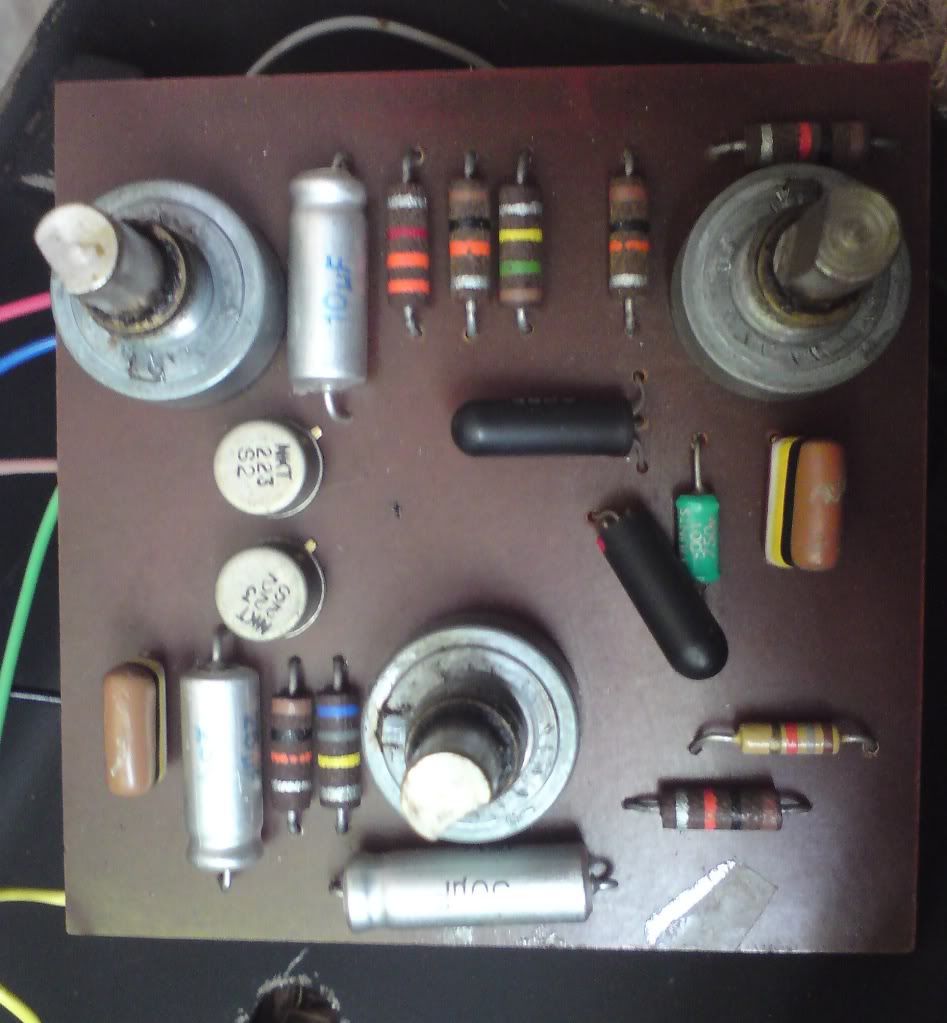
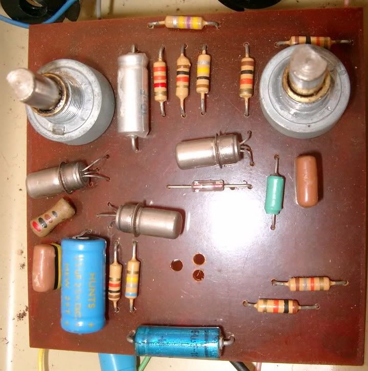
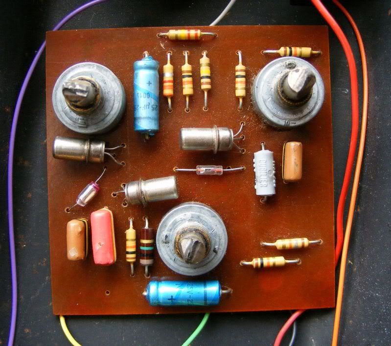
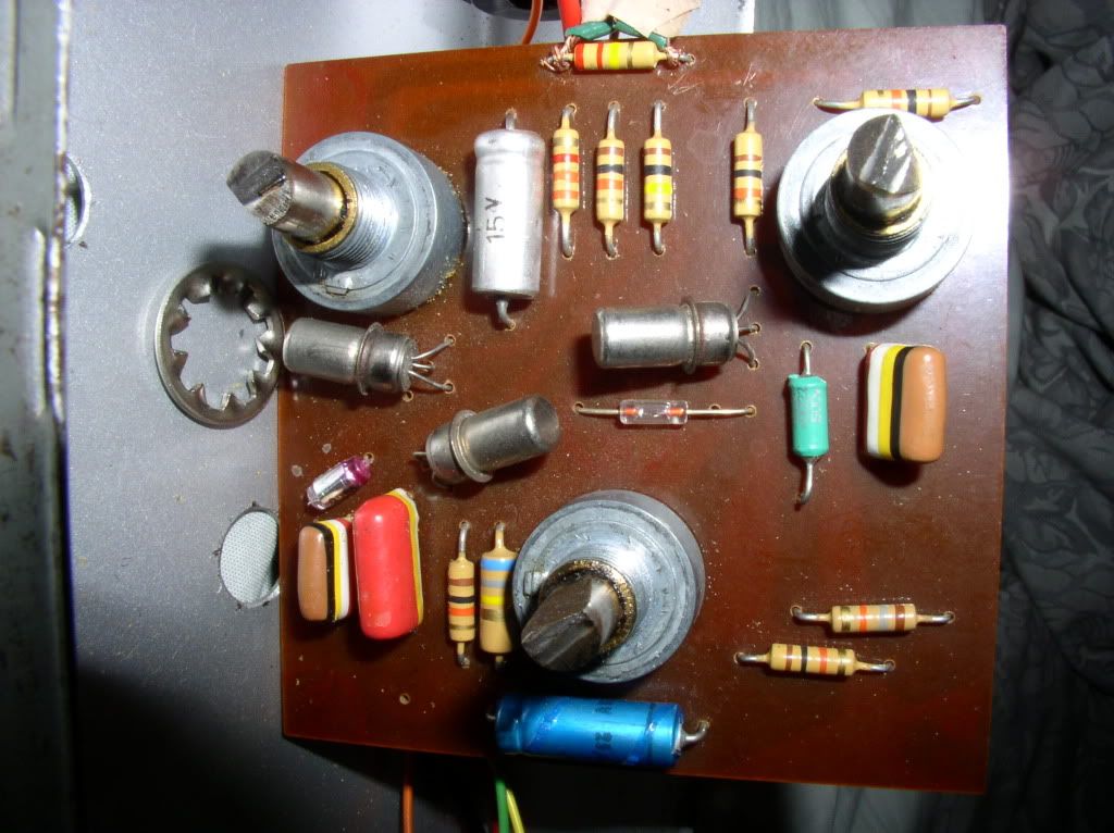
Here are some more MKIII/MKIV circuits I found pics of and the others already posted all put together for reference...
Roto
Vox MKIII
and other Vox MKIII
another early Vox MKIII
Park 2 knob of G's...
Steve's Park 2 knob

Other Roto
NOS Vox MKIII
MKIV that Graham has...?
Stu's MKIV

My 'white hot' MKIV, I posted this before...but here now for reference...
Stu's MKIII
Steve's Orange and Silver MKIV
MKIII with non reverse layout (MKV?) Has a lot of components!! Two diodes?? I think this is the other one G got..?
Steve's 'Hastings' Vox MKIII

G's Silver/Orange non reverse MKIV
2 Yellow TBs that Marty has(had?)
That's all I can find...but should be nice to have them all in one place...I also tried to put them in order of age. (Just a guess...)
Roto
Vox MKIII
and other Vox MKIII
another early Vox MKIII
Park 2 knob of G's...
Steve's Park 2 knob
Other Roto
NOS Vox MKIII
MKIV that Graham has...?
Stu's MKIV
My 'white hot' MKIV, I posted this before...but here now for reference...
Stu's MKIII
Steve's Orange and Silver MKIV
MKIII with non reverse layout (MKV?) Has a lot of components!! Two diodes?? I think this is the other one G got..?
Steve's 'Hastings' Vox MKIII
G's Silver/Orange non reverse MKIV
2 Yellow TBs that Marty has(had?)
That's all I can find...but should be nice to have them all in one place...I also tried to put them in order of age. (Just a guess...)
Last edited by theemadcap1 on Mon Aug 09, 2010 11:44 pm, edited 2 times in total.
-
dazed and confused
- Posts: 1943
- Joined: Tue Aug 26, 2008 9:50 am
- Location: Surrey
Re: Rotosound Mark III
Great thread Madcap and lovely Roto you have there.
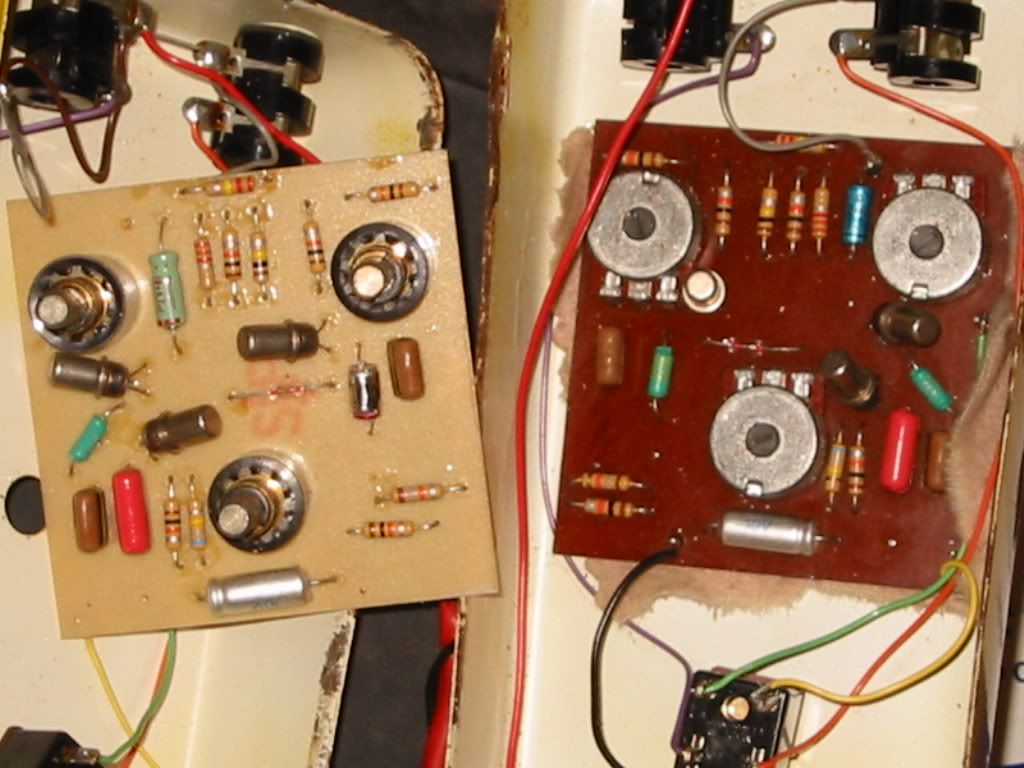
I have one or two MKIII's hanging around:-
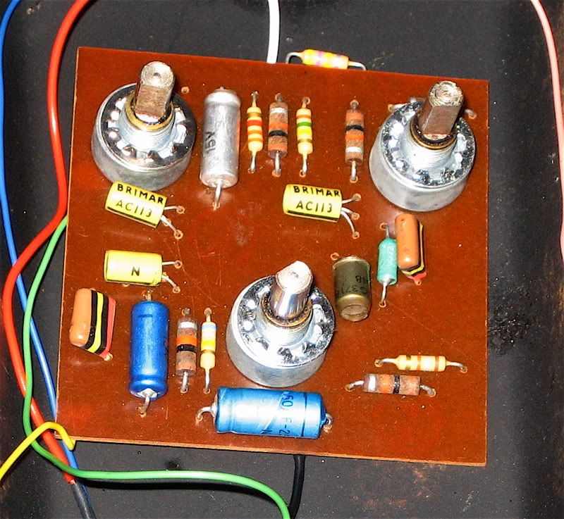
Vox MKIII
Transistors are Newmarket AC128's and OC71
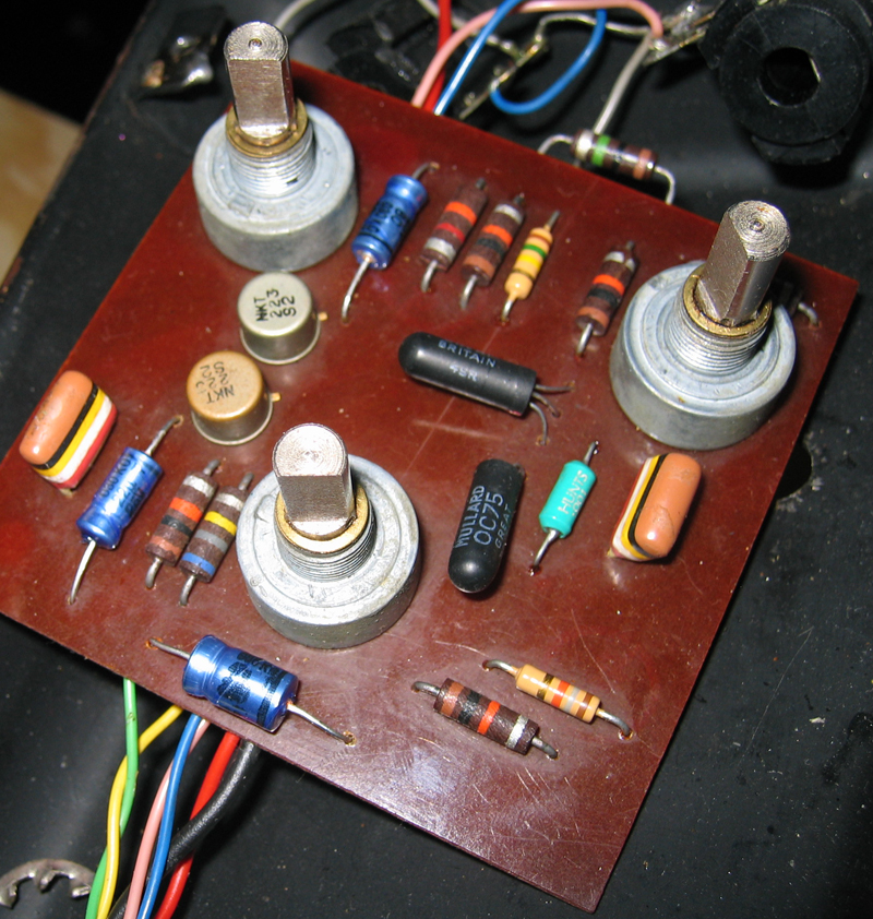
Colorsound MKIV (silver case) reverse board

I might have one or two other MKIII's kicking around, including a 2 knob Park, but it is virtually identical to the one in the post above.
I have one or two MKIII's hanging around:-
Vox MKIII
Transistors are Newmarket AC128's and OC71
Colorsound MKIV (silver case) reverse board
I might have one or two other MKIII's kicking around, including a 2 knob Park, but it is virtually identical to the one in the post above.
-
Laundromat
- Posts: 2673
- Joined: Wed Mar 18, 2009 4:13 pm
- Location: Finland
Re: Rotosound Mark III
Can you tell which position is which?dazed and confused wrote:Vox MKIII
Transistors are Newmarket AC128's and OC71
Condolences, the bums lost!
-
theemadcap1
- Posts: 985
- Joined: Sat Sep 20, 2008 11:25 pm
Re: Rotosound Mark III
Nice ones! Is that a silver and orange 'Batman logo' Tone Bender with a reverse circuit? It has an Iskra cap that has a date code that looks like "321", which would either be 21st week of '73 (?) that would be a later reverse board or maybe it's 32nd week of 71...?...
Post as many MKIII circuits as possible, even if they are very similar, it would be cool to see if there are any differences at all on the boards. Those particular Iskra caps seem to have date codes on them. Seems like (my conjecture) '71 was the year that SolaSound went from the reverse to the non-reverse circuit. It seems like all the different MKIVs (Park, Carlsboro, et al) first had reverse circuits in them. I have heard of a Park reverse board, but have not seen one. I have a picture somewhere of a reverse board Colorsound 'Power Boost'...they must have bought a bunch of those metal Erie pots! Not as many of the white Erie pots, those seem like 69-71...? Maybe they had to work through the circuits and components they had, before they switched to the non-reverse circuit. I don't think I have seen two early MKIII/IV circuits with the exact same components. Some are very similar, but have the odd one or two components. Definitely seems like the use of those light green "Raynex" caps was the start of the transition to the non reverse circuit. Seems like they were in constant flux with the build on these....
Post as many MKIII circuits as possible, even if they are very similar, it would be cool to see if there are any differences at all on the boards. Those particular Iskra caps seem to have date codes on them. Seems like (my conjecture) '71 was the year that SolaSound went from the reverse to the non-reverse circuit. It seems like all the different MKIVs (Park, Carlsboro, et al) first had reverse circuits in them. I have heard of a Park reverse board, but have not seen one. I have a picture somewhere of a reverse board Colorsound 'Power Boost'...they must have bought a bunch of those metal Erie pots! Not as many of the white Erie pots, those seem like 69-71...? Maybe they had to work through the circuits and components they had, before they switched to the non-reverse circuit. I don't think I have seen two early MKIII/IV circuits with the exact same components. Some are very similar, but have the odd one or two components. Definitely seems like the use of those light green "Raynex" caps was the start of the transition to the non reverse circuit. Seems like they were in constant flux with the build on these....
Who is online
Users browsing this forum: No registered users and 8 guests